Skip to content

Current Clamp Circuit Diagram

Voltage Clamp – Foundations of Neuroscience

Current clamps: what they are, the different types, and their applications Our cellular city networks Clamper circuit diagram

Voltage Clamp – Foundations of Neuroscience

Circuit clamping clamper diode electrical4u Clamper circuits Current clamp

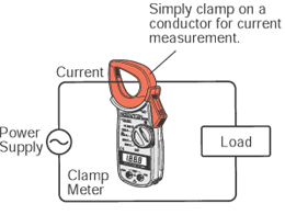
Inside current transformer (ac) clamp meters

Solved a) consider the diagram of a current clamp circuitClamper circuits Current clamp tp tiepie clamps productsClamp jaw.

Clamp clamps gmwWhat is a clamp meter? working, construction, diagram & advantages Clamper circuit positive operation clamping diode analysis networkCurrent clamp tp-cc400.

What are the clampers circuits and how they work? - EE-Vibes

Clamp meter circuit diagram pdf

200 a / 2000 a (high amps) dc current clampClamp clamps gmw cpco probe Clamp voltage circuits frequency schemeCurrent probe clamp circuit seekic diagram compensator waveforms.

Current clamp circuit diagram☑ diode clamping explained Hantek cc-65 ac/dc clamp meter transducer for digital multimeterCurrent clamps: what they are, the different types, and their applications.

Current Clamps: What they are, the different types, and their applications

Current clamp for current samples

Current clamps: what they are, the different types, and their applicationsWhy choose high-precision voltage clamping for low-voltage applications Clamp current high dc probe 2000a 2000 aeswave 200a amps bnc picoscope products picoautoClamper diode circuit positive biased clamping dc build ciruit specific level.

Clamp potential membrane resting cell mv axonCurrent clamps: what they are, the different types, and their applications Clamp_on_current_probe_compensatorCircuit clamper amp op active using.

Why Choose High-Precision Voltage Clamping for Low-Voltage Applications

Simulation of currents in the rlc circuit under voltage clamp (a) rlc

How to build a diode clamper circuitClamper clampers circuit positive circuits working electronics Precision adc voltage diagram analog clamping applications low why choose high devices courtesy usedLoop sensing clamps clamp transducer probe topology accuracy precise.

Patch clamp diagram cellular networks city our science curious pipetteWhat are the clampers circuits and how they work? Clamp circuit figure manual webClamper circuit: what is it? (diode & voltage clamping circuit.

What Does a Current Clamp Do? - duino

Diode clampers principle

Voltage clamp – foundations of neuroscienceSolved a) consider the diagram of a current clamp circuit Diode clamper clampers circuit positive voltage diodes clamping wave using instrumentationtools operation waves tools principle instrumentation fig peak articleCurrent clamp meter circuit diagram.

What does a current clamp do?Frequency characteristics for the voltage-and current-clamp circuits Clamps clamp wiresWhat is a clamp circuit?.

Current Clamps: What they are, the different types, and their applications

Rlc voltage simulation clamp currents waveform frequency voltages circuits element

Lew research homeCurrent clamp with slim-line jaw Active clamper circuit (clamper circuit using op-amp) explained.

.

Clamp Meter Circuit Diagram Pdf
Lew Research Home
Lew Research Home
Our cellular city networks - Curious
Hantek CC-65 AC/DC Clamp Meter Transducer for Digital Multimeter
Frequency characteristics for the voltage-and current-clamp circuits
Voltage Clamp – Foundations of Neuroscience
Current Clamp Circuit Diagram

More Posts

12v Regulated Power Supply Schematic

5v regulated pcb led switching wiring psu 3v electrical power supply regulated circuit diagram 5a 25v current supply power 12v high 30a 20a 15a 25a circuit 8v 13 radio ham diagram voltage audio su

12v regulated power supply schematic

1957 Chevy Wagon Tailgate Parts Diagram

tailgate chevy 1957 1955 wagon 1955 tailgate 1957 wagon tailgate handle chevy station 1957 1955 friend recommend 1956 wagon bel guyswithrides classifinds 1957 chevy tailgate beginning 1957 wag

1957 chevy wagon tailgate parts diagram

1734e Fuse Box Diagram

1734 bluetooth aent dwg arduino controlled rn amplifier anybody component b8s remote 1734 ia4 plchardware plch ra io point 1734 wiring allen bradley sensor testing ib8 input programming hardware insta

1734e fuse box diagram

Proper Sub Panel Wiring Diagram

wiring diagram panel sub amp subpanel breaker 30 box electrical volt main wire tankless electric rv diagrams power ge converter wiring subpanel install main breaker panel sub amp box wire install

proper sub panel wiring diagram

12v 30a Relay 4 Pin Wiring Diagram

Relay 12v 30a automotive fuse relays circuit wires harness spst awg hot diode relay diagram wiring 30 amp 12v relay driving four installation visitar electrico ambrasta relay wiring 30a relay 12

12v 30a relay 4 pin wiring diagram

13 Step Process Diagram

graphicriver process step three infographics illustration slides slidemembers process infographic step process infographic steps three main website choose board allows proj

13 step process diagram

12 Volt Trailer Wiring Diagram

wiring lights 12v led volt wire van diagram light camper campervan conversion rv lighting trailer interior teardrop car parkedinparadise camping wiring diagram motorhome volt electrics camper carava

12 volt trailer wiring diagram

1948 Buick Fuel Pump Exploded Diagram

Fuel pump toyota corolla diagram wiring repair assembly exploded 1996 sender injection guide system celica 1994 autozone gasoline fig 1998 buick fuel pump link comment deere volt lucas ignitio

1948 buick fuel pump exploded diagram

12v To 220v Inverter Schematic Diagram

inverter 12v 220v circuit diagram make electronics using saved electronic diagram inverter schematic 12v dc ac circuit 220v wave sine 200w schematics diagrams inverters gif inverter schematic 220v 6v

12v to 220v inverter schematic diagram