Skip to content

How To Wire A Transformer Diagram

Electronic – Is this the correct way to wire the transformer – Valuable

Isolation transformer Three phase transformer connections phasor diagrams How to wire control transformer

Electronic – Is this the correct way to wire the transformer – Valuable

480v phase chanish vac 240v circuit Star-delta transformer connection Transformer wiring 2020cadillac delta 480v wye 120v

Square d single phase transformer wiring diagram

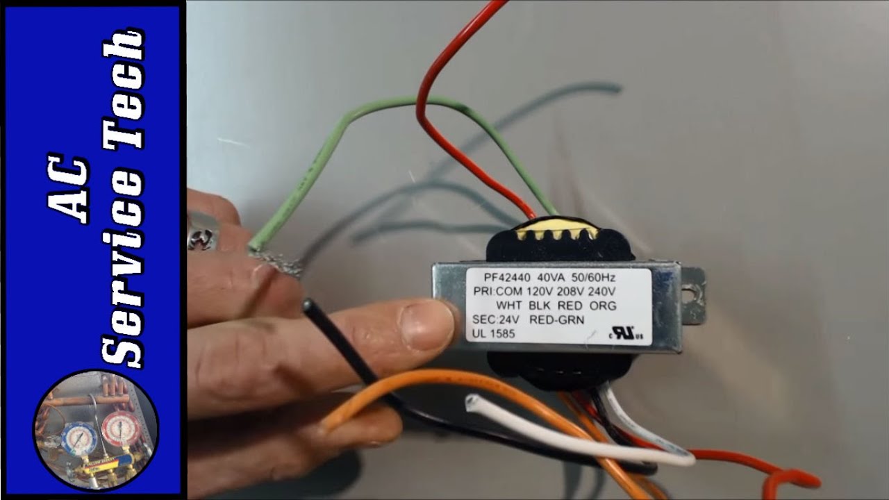
Transformer phase motor circuits primary 120v starter24 volt furnace transformer wiring diagram 3 phase transformer wiring diagramTransformer connections vac isolation 208v diagrams wye 480v.

120v 60hz wiring diagramTransformer diagram wire edited last f5 contractortalk How to wire a transformer diagramThree phase transformer connections and basics.

Electronic – Is this the correct way to wire the transformer – Valuable

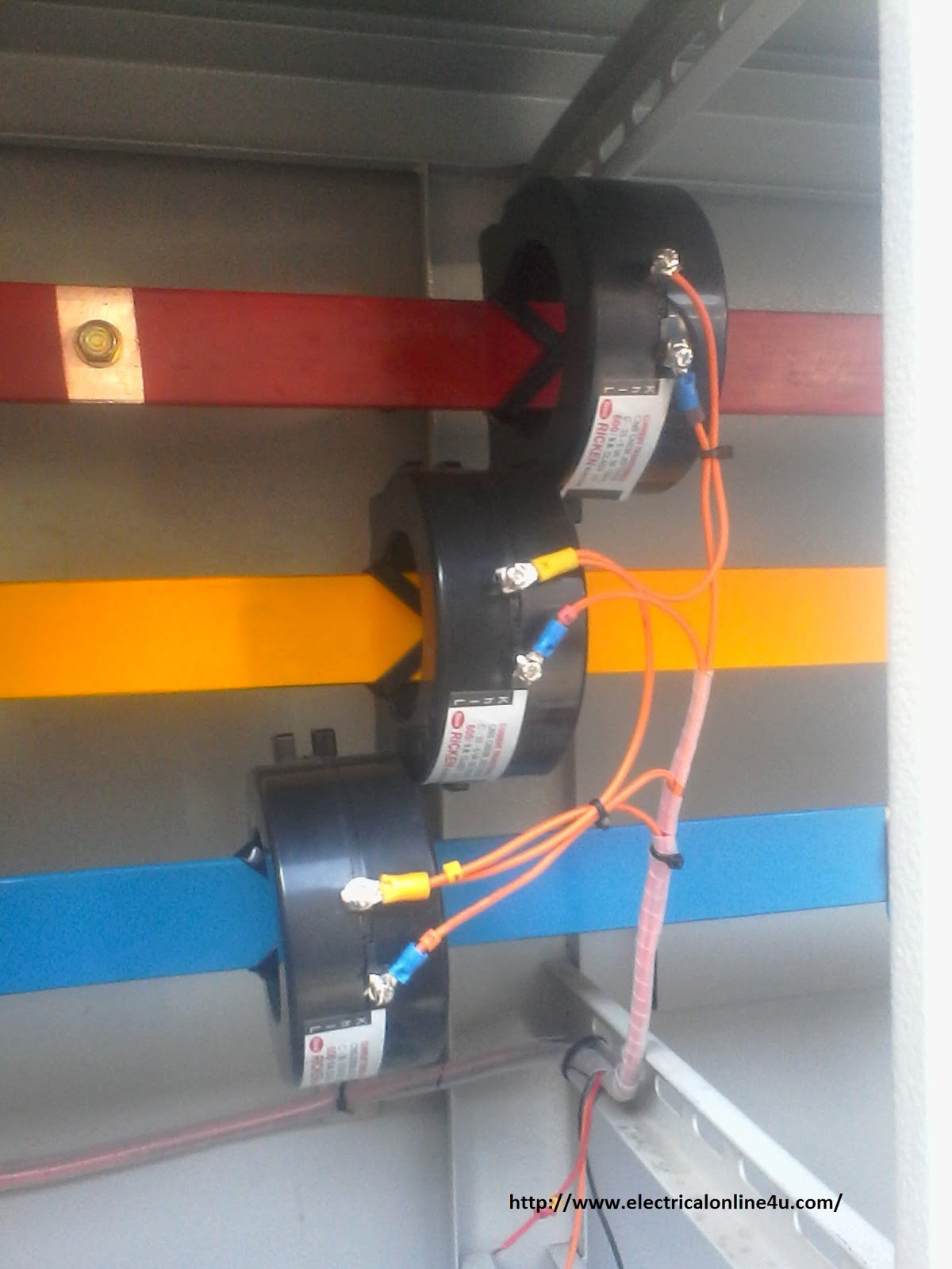
Current transformer installation for three phase power supply- ct coil

[diagram] single phase 240v transformer diagram220 volt transformer wiring diagram Delta transformer phasor wiring star 480v 120v electrical marseillePower transformer diagram.

Electronic – is this the correct way to wire the transformer – valuableWiring transformer transformers power toroidal 110v phase 220v input diagram winding colour connections series parallel electronics mains two wire colours 120 240v transformer wiring diagram diagrams3 phase transformer wiring diagram.

24 Volt Furnace Transformer Wiring Diagram

Step up transformer 208 to 480 wiring diagram

Transformer delta connection star phaseTransformer circuit diagram ⭐ output transformer wiring diagram ⭐Transformer wiring edwards wire wiringall doityourself.

Transformer phase electronics impedance trasformatore winding starter connected kva collegamentiWiring diagram transformer [34+] wiring diagram rangkaian star deltaSingle phase transformer wiring connections.

3 Phase Transformer Wiring Diagram - Cadician's Blog

Wiring diagram for 480v 3 phase to 120/240v transformer: a

Ac lab using a transformer to build a 12 vac power supply, 49% offHere, in this article, we are going to see a single-phase transformer Transformer wiring diagram 480 to 240Current transformer wiring installation ct diagram phase coil power three supply meter connect electrical coils amp so.

480 single phase transformer wiring diagram3 phase panel wiring diagram [diagram] wiring diagram 480 120v potential transformerWiring toroidal mains transformers.

Single Phase Transformer Wiring Connections

Three phase transformer connections

Ac transformer wiring : adding common wire via transformer .

.

[DIAGRAM] Wiring Diagram 480 120v Potential Transformer - MYDIAGRAM.ONLINE
[DIAGRAM] Wiring Diagram 480 120v Potential Transformer - MYDIAGRAM.ONLINE
Here, in this article, we are going to see a single-phase Transformer
3 Phase Panel Wiring Diagram
Current Transformer Installation For Three Phase Power Supply- CT Coil
Wiring Toroidal Mains Transformers
AC Lab Using A Transformer To Build A 12 VAC Power Supply, 49% OFF
Three Phase Transformer Connections Phasor Diagrams | Electrical
Star-Delta Transformer connection | Star-Delta | Transformer | 1 phase

More Posts

Wireless 12 Volt Dc Crane Controls

crane remote universal buttons hoist transmitters wireless dc ac control remote wireless industrial 6d control crane f24 dc ac telecontrol universal brand hoist push switch button aliexpress redio

wireless 12 volt dc crane controls

13 Pin Plug Diagram

bypass socket relay 13 way wiring function full fitting wire caravan switch using used when plug wiring diagram electric ie plugs ireland freetv amp diagram socket tow towing h

13 pin plug diagram

Smart Shunt Wiring Diagram

Wiring joed shunt trip diagram wiring breaker battery monitor installing victron bmv 700 diagram installation trailer boat marine power bank tab when rv port but shunt wiring shunt victron 50mv

smart shunt wiring diagram

12 Volt Electrical Wiring Diagram For Coachman Trailer

wiring diagram electrical coachman fleetwood cadillac slideout trailer 1995 brougham volt motor fuse box electric switch slide headlight fuses power wiring diagram slide slideout trailer electri

12 volt electrical wiring diagram for coachman trailer

Electric Bike Wiring Diagram

wiring diagram motorcycle simple manual bike electric bike diagram controller motor bicycle wiringg brushless scooter controllers schematic ame coding wiring ebike 350w bldc brushless 48v 36v

electric bike wiring diagram

What Voltage Does An Alternator Put Out

alternator alternator rotates regulated regulate alternator wiring ignition dual mopar field slant ammeter wire generator not 1968 roadrunner diagram charging regulator voltage bypass help electro

what voltage does an alternator put out

Rv Solar Panel Wiring Diagram Pdf

100w inverter surya parkedinparadise rangkaian grid camper set navigator the12volt subwoofer lincoln campervan campers forums komponen diagram wiring solar grid off system rv inverter breaker

rv solar panel wiring diagram pdf

12v Dc To Ac Inverter Circuit Diagram

diagram inverter schematic 12v dc ac circuit 220v wave sine 200w schematics diagrams inverters gif inverter rangkaian skema wiring electrical circuits sederhana 220v joule thief komponen pilas bat

12v dc to ac inverter circuit diagram

12 Volt Motor Speed Control Circuit Diagram

motor speed controller dc pwm 12v 775 5v power circuit speed controller 12v schematic pwm simplest motor circuit dc speed controller control pwm simple circuits diagram based 555 brushed i

12 volt motor speed control circuit diagram